| The Bricklin Int'l Tech. Central Editor is John T.
Blair. To forward comments, questions, or corrections, email techcentral@bricklin.org Return to the Tech Central Section Home |
 Contact Webmaster |
|
Tearing down the front suspension(from Notes on Restoring Bricklin #887) Originally written: 1994Last updated: 12/17/04
©By: John T. Blair (WA4OHZ)
In this article I’ll discuss pulling down the front suspension of the Bricklin. If you don't want to pull down the entire suspension, you might find some of the information handy as this will also cover replacing disk pads, removing the front hubs, repacking the bearings, removing the shocks and installing ball joints. Before any work is started on the front end, you should be aware that if you replace a part on one side of the car, you should perform the same work on the other side. It also helps if you take apart one side at a time. This way you can always look at the other side to see how things go back together. A lot of the work performed on the front end will require a front end alignment after the work is complete. Also some jobs, such as replacing the bushings on the upper and lower control arm may require the services of a machine shop. The reason for mentioning this is to help you plan your work. Don't start a job on a Sunday afternoon if you need the car Monday and can't get the car aligned or can't get the bushings pressed out because all the shops are closed.
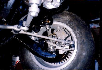
If both sides are going to be rebuilt, both front wheels will have to be removed, otherwise only remove the desired wheel by removing the 5 lug nuts.. (Note: For the novices I have presupposed that you have a 1/2" drive impact hammer, an air compressor and that the lug nuts are not on too tight. If you don't have an impact hammer or the lug nuts are really on, the car will have to be on the ground to break the lug nuts loose. You'll have to get out the really big guns, a 1/2 drive tommy bar and a 4 to 6 foot length of pipe that will fit over the handle of the tommy bar. Put the socket on the nut, slide the pipe over the end of the tommy bar and then pull.) Now the suspension is exposed. This is the starting point for most of the work on the front suspension and brakes. Now is a good time to visually check the front brakes. Ensure there is at least 1/16" of braking material between the pad backing and the disks. If not, it is time to replace the disk pads. Also check the flexible brake line that connects the calipers to the main steel hydraulic lines for cracks or leaks. If the line is cracked, replace it. If any leaks are spotted, it indicates the connection is loose and needs to be tightened. It is probably worth noting at this point that brake fluid is very caustic to paint. In other words it makes a great paint remover. Be careful not to get the brake fluid on any painted surfaces. If you do, wipe it off immediately. The 74 and early 75 Bricklins used Kelsey Hayes calipers (EIS Brake, a division of Standard Motor Products, Inc #RC6030 (left) and RC6029 (right)). These calipers can be found on 71 to 75 Hornets and Gremlins, and 71-75 Pacers. The later Bricklins used the Bendix calipers. Removing the Calipers After the front of the car is in the air, supported by jackstands and the front wheels have been removed, the calipers can be take off. There are 2 bolts that hold the caliper to the adapter bracket, but these bolts can be difficult to see. To gain maximum access to the caliper mounting bolts, turn the steering wheel toward the side of the car you want to work on. If the caliper is to be replaced, or removed for painting, the flexible brake line will also have to be removed, otherwise the caliper can be slid off the rotor and tied up, out of the way, with some wire.
Helpful hint: There is a special type of wrench called a "flare wrench" for removing brake lines. This wrench is a box end wrench with a slot cut in the box. This way the wrench will fit over the brake line and have maximum contact area with the "bolt" that holds the line into the caliper (wheel cylinder or master cylinder). If the "bolt" is very stubborn, the flare wrench might have a tendency to open and slip. To stop this, try using a pair of vise grips to clamp the flare wrench tight. If all else fails, use the vise grips on the "bolt" to break it loose. Replacing the Pads To replace the brake pads, the caliper has to be removed from the car. There are 2 bolts that hold the pads in place. Simply unscrew the bolts and remove them from the calipers, and the pads will lift out. To install new pads, simply insert them into the caliper, (with the metal backing plate towards the outside of the caliper) and insert the pad bolts. The caliper can be remounted to the adapter bracket. Removing the Hub/Rotor To remove the hub/rotor, both the wheel and caliper will have to be removed before the hub can be removed. The hubs are held in place by a nut, a nut lock, and a cotter pin. However, these are hidden by the dust cover. The dust cover is held in place by a force fit. In other words, it is simply pressed on. There are 3 ways to remove the dust cover, (1) use a screw driver and try to pry it off, When the dust cover comes off, the cotter pin, nut lock and nut will be visible. The cotter pin goes through the axle and keeps the nut from loosening and letting the wheel fall off. The nut lock is a thin metal piece that looks like a castled nut and fits over the nut. Once the cotter pin is out, the nut lock can be pulled off and the nut can be unscrewed using a wrench or socket. The hub rides on 2 bearings, called an inner (the larger, closest to the center line of the car) and an outer (the smaller). Grab the hub with one hand and hold the other hand underneath and in front of the axle. Wiggle the hug and the outer bearing should fall out in your hand. This will allow the hub to be pulled off its axle. Place the outer bearing, washer, nut, and nut lock on a clean rag or paper towel. Remember, dirt is a mechanics worst enemy! If the steering wheel shakes when you step on the brakes, the rotors are extremely rusty, or if there are any deep groves or scratches on the rotors, they should be turned (machined flat so the sides are parallel). Before the rotor(s) can be sent out to be turned the bearing races (the part that the bearing sits in) and grease seal(s) may have to be removed. Call the shop that is going to do the work for you and find out whether they want the bearings and races, or do they just want the hub. Also be sure to tell them the rotors are part of the hub and not removable. (Many cars today have separate rotors and hubs. Consequently, only the rotors have to be sent to the machine shop. The easiest way to remove the inner bearing, rear grease seal, and races is to use a slide hammer and gear puller. If you don't want to purchase or rent one of these pullers, you can use a hammer and a punch/drift. Set the hub/rotor on some scrap 2x4s with the bearing pointing down and place a clean rag or paper towel under the hub to catch the bearing. Remember - dirt..... Place a drift (steel rod) through the center hole where the outer bearing was. Now, gently tap the inside edge (nearest the center of the hole) of the bearing. Move the drift about 1/4 of the way around the bearing and tap it again. Keep moving the drift 1/4 of the way around the bearing and tapping it until it falls out. Before the hubs are put back on the car, they should be thoroughly cleaned to remove all the old grease and repacked (put new grease in them). A good cleaning solvent is Varasol. It doesn't evaporate too fast and can be reused. Its only draw back is it is expensive!. The last gallon I purchased, about 3 years ago, was almost $4. To clean the bearings, put some solvent in a small can and brush the bearing until the grease is out of it. Now examine the rollers for chips, pits and discoloration. Place two fingers in the center of a bearing and slowly rotate it. If it feels gritty, (like it is rolling on sand) it should be replaced. To repack the bearings some people use their hands and push grease into the bearings. I prefer using a bearing packer. One can be purchased for under $10 at the local auto parts store or from J.C. Whitney. If new bearings are to installed, the old races (the part that the bearing turns in) will have to be removed. This is similar to removing the inner bearing except that instead of tapping on the bearing, you tap on the edge of the race itself. Removing the outer race is similar, only set the hub on the wood with the outer race pointing down. To install a new race, place it on the hub. Take a strong board or metal bar and lay it across the race. Hit the board to start the race into the hub. Continue tapping the wood until the outside edge of the race is even with the outside edge of the hub. At this point, you will have to use a punch or drift to continue pressing the race into the hub. Be very careful when hitting the drift with the hammer. You don't want the drift to slip off the outer lip of the race and scratch the machined surface that the bearing sits in. Continue tapping the race into the hub until it seats against the little sill or lip. Repeat this procedure with the other race. Now the hubs/rotors can be sent out to be cut, turned or trued. Replacing the Front Shocks
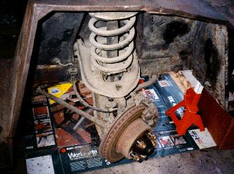
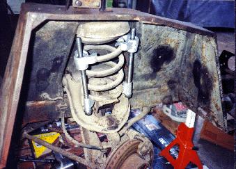
Start by jacking the car up, remove the front wheels and open the hood. Remove the 2 nuts from the bottom of the shocks. These nuts can be difficult to get to as they are under the lower spring seat. Try placing a jack under the lower ball joint and jacking it up. This will raise the upper control arm and give better access to the rear shock mounting nut. Next, remove the 2 bolts from the top of the shock which is located in the engine compartment. Finally, remove the 3 nuts that hold the upper shock mounting bracket to the top of the inner fender well and the 2 bolts that attach the shock mount to the side of the fender well. The shock can now be lifted up though the fender well and out the engine compartment. Installing the new shock is reverse. However, I suggest that you extend the shock before you set it through the fender well. If it doesn't reach the lower mount, jack up the suspension with a floor jack. One word of caution, be very careful working of the suspension if you have jacked it up. The spring has been compressed and if the jack slips, the suspension will expand. If your hand is between any parts, you could loose your hand! Removing the Coil Springs Before you can remove the coil spring, the wheel, hub, caliper and the shock will have to be removed. You will also need a coil spring compressor. I purchased a standard spring compressor from Harbor Freight for about $10. In the local area, you can rent one from most auto parts stores. After the other parts have been removed, you must remove the nuts from the spring seat spindle. The bolts appear to be splined and do not turn or come off this piece. Install the spring compressor and compress spring. If you are lucky, the spring will lift off the spring support and can be pulled out. If not, you will have to compress the spring until the spring support can be removed and then the spring can be pulled out. A couple of foot notes should be added at this point.
1. Remember that the spring stores energy. Therefore, be very careful when working on the spring and do not get your hand between the spring and anything. 2. When compressing the spring, take a couple of turns on one side of the spring compressor, then do the same thing on the other side. 3. If the compressor starts to slip down the coil, clamp a pair of vise grips on the coil in front of the spring so it can't slip. 4. Installing the spring proved to be more difficult than taking it out.
5. I've never seen one, but I've been told that AMC has a special spring compressor. It is a plate that fits over the shock mount, a rod goes down into the spring and another plate slides into the spring and attaches to the rod. As the rod is turned, the spring will compress. The reason for mentioning this compressor is that the idea seems simple. An enterprising hobbyist could try to make one. (I finally modified an internal spring compressor that is used on Ford Mustangs.) Removing the Upper Control Arm
To replace the bushings for the upper control arm, the control arm will have to be removed. Start by removing the cotter pin and nut from the upper ball joint. While this sounds simple (I usually use a pneumatic impact wrench, I couldn't get the socket into the nut.), as I pulled on the wrench to loosen the nut, the spindle turned. If I kept turning, the backing plate would have hit the chassis and bent. To avoid this, I turned the wheels so the spindle (axle) was parallel to the chassis. Then I tied the axle in place by making several passes around the axle and the chassis with a rope . Now the ball joint's nut could be broken loose and removed. You will have to pop the upper ball joint loose from the steering knuckle. Refer to Popping ball joints at the end of this article. Once popped, the steering knuckle can be moved out of the way. There are 2 nuts and bolts attaching the control arm to the shock tower. Once the nuts are removed, the bolts will require some coaching to remove them. Replace a nut on the end of a bolt to protect the threads and tap the nut with a hammer. When the nut is touching the tower, remove the nut. At this point, either try driving the bolt out by hitting the threaded end with a hammer and drift or place an open end wrench, just large enough to fit over the shaft of the bolt, next to the bolt head. If the second wrench method is used, apply pressure to the head of the bolt and continue turning the bolt until the bolt come out. After the bolts are removed, the upper control arm can now be pulled out of its seat. Depending on the shape of the front suspension (i.e. very rusty) replacing the bushing can be quite a bit of work. It will make the job a lot easier if you have access to a press. (Note: A nice hydraulic press can be purchased for about $100 from some of the mail order houses.) The old bushings can be pressed out and the new ones pressed in. If you don't have a press, then the job is a lot harder. You might want to talk to a local garage and see what they'd charge to press the bushings for you. Doing the job by hand will require a large hammer, and some blocks of wood. Place the control arm on the blocks and try to drive out the old bushings with the hammer. For bushings that have almost fused to the control arm due to rust you have to work a lot harder. I suggest using an electric drill and a drill bit that is smaller in diameter than the distance from the inner metal tube and the outer tube. Let the drill cut away the rubber until the center tube of the bushing can be removed. Using a hacksaw, carefully cut a slit in the outer bushing. Be careful not to cut into the control arm. Drive a chisel between the remaining part of the bushing and the control arm. This will cause the outer tube to collapse into the center of the control arm's mounting hole. Eventually, it can be pulled out of the control arm. Removing the Upper Ball Joint If the car has not had the original upper ball joint replaced, the ball joint will be held in place with rivets. To get access to the upper ball joint, the wheel, hub, and caliper should be removed. While the upper control arm doesn't have to be removed from the vehicle, I don't recommend leaving the control arm on the car if the ball joints haven't been replaced. Getting the rivets out while the control arm is still on the car can be a real pain. The best way to remove them is to drill them out. I had removed the control arms and decided to work from the bottom side of the rivets (it was the thinner side). I drilled a small pilot hole (3/32" dia.) then drilled a larger hole. Don't try to drill all the way through the rivet because you will probably not be centered and you will wallow out the hole in the control arm. When the hole in the rivet is deep enough to be through below the control arm, I used a chisel and a hammer to cut off the bottom of the rivet. Then I used a drift or punch to knock the rivet out of the hole. If the rivet will not come out, drill the hole in the rivet a little deeper. The replacement ball joint should come with 4 grade-8 bolts and nuts. To install the new ball joint simply set it in place and install the 4 nuts and bolts and tighten. Removing the Tie Rod End The tie rod ends are the easiest part to work on. After the car is jacked up and on stands, remove the cotter pin, loosen the nut and pop the ball joint loose. If you are going to replace the tie rod end, you will also have to loosen the nut and bolt that hold the end to the adjusting tube. Once the parts are replaced it will be necessary to have the front end aligned. Removing the Lower Ball Joint Before you can remove the lower ball joint, the wheel, hub, and caliper will have to be removed. To gain access to the nut for the lower ball joint you will have to remove the two nuts that hold the steering arm to the tie rod end. The steering arm can be pushed aside, the cotter pin removed and the ball joint nut can be loosened. Here again, it might be necessary to tie the axle to the chassis with rope as described in "removing the upper control arm. After the nut is loosened, the rope can be removed. Turn the axle to allow greater access to the ball joint seat at the bottom of the steering knuckle. Pop the ball joint and push the steering knuckle out of the way. The rivets that hold the ball joint in place are now exposed and can be removed as described in removing the upper ball joint above. Again the new ball joint should come with bolts to replace the rivets. Simply remove the old ball joint, insert the new ball joint and bolt it into place. Removing the Lower Control Arm
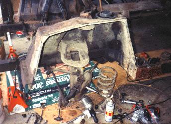
Before the lower control arm can be removed, the wheel, hub, caliper, steering arm, must be removed and the lower ball joint must be popped from the steering knuckle. The steering arm is removed by undoing the 2 bolts that attach it to the steering knuckle pin. After removing the cotter pin the ball joint's nut, I tied the spindle in place (see removing upper ball joints above). The strut rod is attached to the top of the lower control arm by 2 bolts and nuts, which must be removed. The sway bar will also have to be removed by removing the nut from the bottom of the link bolt. (This may be more difficult than expected if the link bolt has rusted to the standoff rod. I had to cut off the link bolt with a cutting wheel on a die grinder.) Now all the paraphernalia has been removed. All that is left is to remove the pivot bolt that attaches the control arm to the front cross member. The head of the bolt must be held in place as the nut is removed. The bolt sits in 2 washers, one on either side of the chassis cross member. These washers are specially cut to form an eccentric so camber can be adjusted. After removing the nut from the bolt, it might be necessary to drive the bolt out of the bushings. If this is required, ensure the nut is on the bolt so that the outer edge of the nut is flush with the end of the bolt. This is to protect the threads on the bolt. Using a drift and a hammer, drive the bolt out the front of the cross member. Again, be sure not to loose these washers as they are required when reinstalling the lower control arm. The front end will have to be aligned after performing this procedure.
Removing cotter pins: These little guys can be stubborn critters. One end has a bend in it, this is the head. The other end is 2 pieces of wire, called the tail. When they are installed, the 2 pieces of the tail are bent apart. To remove a cotter pin, the tail must be straightened out and pushed together to realign it with the head. To do this, you'll need a pair of wire cutters (diagonal cutters) and possibly a hammer and a drift. Once this is done and if you are very lucky, you can simply push on the tail and the cotter pin will come out. For the more stubborn ones, you can grab the head with the dikes and pry them out a fraction of an inch using the nut a the fulcrum. Then take another bite with the dikes and pry a little further. Every once in a while, you will have to cut the head and pull the pieces out by the tail. Popping a ball joint: They make a tool for this called a ball joint separator or a pickle fork. These cost about $10 or can be rented. However, I've never used one. My dad showed me how to pop these loose with a hammer years ago by hitting the ball joint seat (the piece that the taper on the ball joint fits into). It usually takes several good wallops for it to pop. Regardless of the method you use, you will have to remove the cotter pin from the ball joint and break the nut loose. If you use the hammer against the seat method, be sure to keep the nut on the ball joint to protect the thread even if you are going to replace the ball joint. This is good practice so you don't trash the thread on a ball joint or tie rod end that you may reuse.
Front Suspension Parts list Return to the Index of Tech. articles |
 First, jack up the front of the car up and place some heavy duty jackstands
under the chassis. I emphasize the heavy duty jackstands because the car weighs over 3500
pounds. (A couple of years ago a fellow in one of the local clubs was killed when the
cinder blocks the car was resting on collapsed.) Chocks (bricks) should be placed in front
and behind a rear wheel, and be sure the car is in park with the emergency brake is set.
First, jack up the front of the car up and place some heavy duty jackstands
under the chassis. I emphasize the heavy duty jackstands because the car weighs over 3500
pounds. (A couple of years ago a fellow in one of the local clubs was killed when the
cinder blocks the car was resting on collapsed.) Chocks (bricks) should be placed in front
and behind a rear wheel, and be sure the car is in park with the emergency brake is set. 
 The car must be
jacked up and supported on jack stands, the wheel, caliper, hub, and coil spring will have
to be removed.
The car must be
jacked up and supported on jack stands, the wheel, caliper, hub, and coil spring will have
to be removed.